Q 1 :    

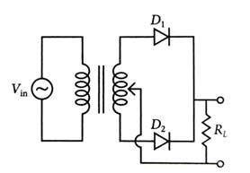
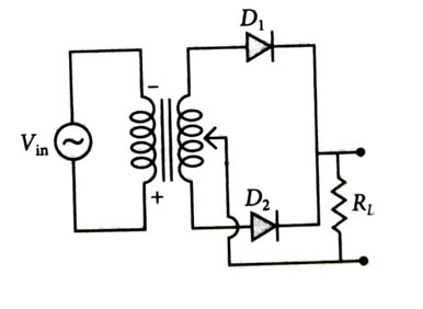
A full wave rectifier circuit with diodes (D1) and (D2) is shown in the figure. If input supply voltage Vin=220sin(100πt) volt, then at t=15 msec        [2025]

  • D1 and D2 both are forward biased


  • D1 and D2 both are reverse biased


  • D1 is forward biased, D2 is reverse biased


  • D1 is reverse biased, D2 is forward biased


(4)

Given that, Vin=220sin(100πt) volt

and t=15 msec

Vin=220sin(100×π×15×10-3)=220sin(32π)=-220V

Hence, D1 is reverse biased and D2 is forward biased.


Q 2 :    

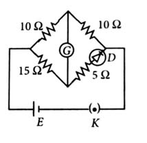
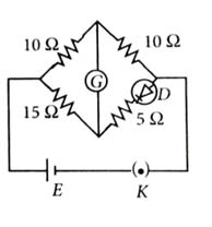
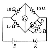
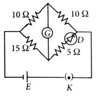
Choose the correct circuit which can achieve the bridge balance.                  [2024]

  •  

  •  

  •  

  •  

(1)

For the bridge to be balanced, the arm containing diode should have 15 Ω resistance and diode in forward bias. In option (2) and (4), diode is in reverse bias and in option (3) diode is in parallel with a 5 Ω resistance, so effective resistance of this arm is less than 5 Ω. So the correct option is (1) as diode is in series with 5 Ω resistance which can give an equivalent resistance of 15 Ω in case if the diode is considered not ideal.


Q 3 :    

In the given circuits a), b) and c), the potential drop across the two p-n junctions are equal in:             [2022]

  • Circuit a) only


  • Circuit b) only


  • Circuit c) only


  • Both circuits a) and c)


(4)

The potential drop across p-n junction diode is equal when either both are in forward biased or reversed biased. So, in circuits (1) and (3) both are in forward biased.
So, correct option is (4).


Q 4 :    

In a p-n junction diode, change in temperature due to heating               [2018]

  • affects only reverse resistance


  • affects only forward resistance


  • does not affect resistance of p-n junction


  • affects the overall V-I characteristics of p-n junction.


(4)

Due to heating, number of electron-hole pairs will increase, so overall resistance of diode will change.

Due to which forward biasing and reversed biasing both are changed.


Q 5 :    

Which one of the following represents forward bias diode?                 [2017, 2006]

  •  

  •  

  •  

  •  

(4)

A diode is said to be forward biased if p-side is at higher potential than n-side of p-n junction.


Q 6 :    

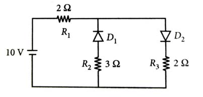
The given circuit has two ideal diodes connected as shown in the figure. The current flowing through the resistance R1 will be           [2016]

  • 2.5 A


  • 10.0 A


  • 1.43 A


  • 3.13 A


(1)

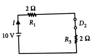
Diode D1 is reverse biased so, it will block the current and diode D2 is forward biased, so it will pass the current.

Hence, equivalent circuit becomes as shown in the figure.

Current in the circuit = Current flowing through the resistance R1

    =102+2=2.5 A


Q 7 :    

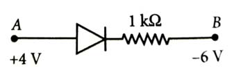
Consider the junction diode as ideal. The value of current flowing through AB is              [2016]

  • 10-1 A


  • 10-3 A


  • 0 A


  • 10-2 A


(4)

Here, the p-n junction diode is forward biased, hence it offers zero resistance.

   IAB=VA-VBRAB=4V-(-6V)1kΩ=101000A=10-2A


Q 8 :    

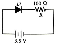
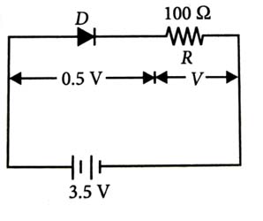
In the given figure, a diode D is connected to an external resistance R=100Ω and an e.m.f. of 3.5 V. If the barrier potential developed across the diode is 0.5 V, the current in the circuit will be

  • 20 mA


  • 35 mA


  • 30 mA


  • 40 mA


(3)

The potential difference across the resistance R is

         V=3.5 V-0.5 V=3 V

By Ohm’s law,

the current in the circuit is  

I=VR=3V100Ω=3×10⁻²A=30×10-3A=30 mA


Q 9 :    

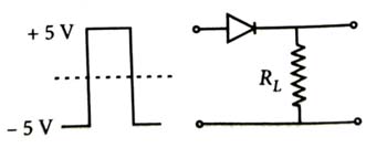
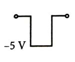
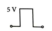
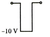
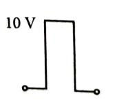
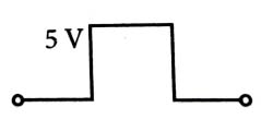
If in a pn junction, a square input signal of 10 V is applied, as shown, then the output across RL will be          [2015]

  •  

  •  

  •  

  •  

(2)

Diode is forward bias for positive voltage i.e. V>0, so output across RL is given by as shown in figure.