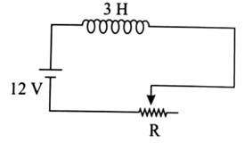


Q 1 :

In the given circuit the sliding contact is pulled outwards such that electric current in the circuit changes at the rate of 8 A/s. At an instant when R is 12Ω, the value of the current in the circuit will be ________ A.          [2025]


(3)

ε–LdIdt–IR=0

12–3×(–8)–I×12=0

⇒ I=3 A


Q 2 :

Three identical resistors with resistance R=12 Ω and two identical inductors with self inductance L = 5 mH are connected to an ideal battery with emf of 12 V as shown in figure. The current through the battery long after the switch has been closed will be ________ A.                  [2023]


(3)

After long time an inductor behaves as a resistance-less path. So current through cell

I=12R/3=3 A    {∵R=12 Ω}


Q 3 :

As per the given figure, if dIdt=-1 A/s then the value of VAB at this instant will be _______ V.                   [2023]


(30)

dIdt=-IAsec

VA-IR-LdIdt-12=VB

VA-2×12-6(-1)-12=VB

VA-VB=36-6=30 V


Q 4 :

In the given figure, an inductor and a resistor are connected in series with a battery of emf E volt. Ea2b J/s represents the maximum rate at which the energy is stored in the magnetic field (inductor). The numerical value of ba will be _________.                            [2023]


(25)

E=12LI2

Rate of energy storing =dEdt=LIdIdt

Now we know for an R-L circuit

        I=ER(1-e-RLt)

So  dIdt=ELe-ttRL

        dEdt=E2R(1-e-ttRL)(e-tRL)

Time at which rate of power storing will be maximum, t=LRln2

So  dEdt=E2R(1-12)×12

⇒  E24R=E2100=E22×50

a=2,  b=50

So  ba=25


Q 5 :

Figure shows the circuit that contains three resistances (9Ω each) and two inductors (4 mH each). The reading of ammeter at the moment switch K is turned ON, is ______ A.  [2026]

  • 2


  • zero


  • 1


  • 3


(3)

Just after closing the switch, inductor will behave as open circuit,


Q 6 :

In the adjoining circuit, initially the switch S is open. The switch ‘S’ is closed at t = 0. The difference between the maximum and minimum current that can flow through the battery is

  • 2 A


  • 3 A


  • 1 A


  • 0.5 A


(3)

imax (After long time)=10V5Ω=2A

imin (at t=0)=1010=1A


Q 7 :

Find the value of instantaneous power (in W) supplied by battery at the moment after the switch is closed.


(1)

P=V2Req  at t=0 (Switch closed)

    =(100)210000=1W


Q 8 :

An inductor of inductance 10 mH having resistance of 100 Ω is connected to battery of E.M.F. 1.0 V through a switch as shown in the figure below. After switch is closed, the ratio of instantaneous voltages across the inductor when the current passing through it is 2 mA and 4 mA is ______.            [2026]

  • 43


  • 34


  • 53


  • 35


(1)

Apply KVL: E-iR-VL=0

VL=E-iR=1-100i

At i1=2×10⁻³ A,  VL1=0.8 V

At i2=4×10⁻³ A,  VL2=0.6 V

⇒VL1VL2=43


Q 9 :

A 30 cm long solenoid has 10 turns per cm and area of 5 cm2. The current through the solenoid coil varies from 2 A to 4 A is 3.14 s. The e.m.f. induced in the coil is α×10-5V. The value α is ______.              [2026]

  • 60


  • 12


  • 120


  • 34


(2)

<ε>=LΔIΔt  (magnitude)

α×10-5=(μ0N2Aℓ)(I2-I1)t

α×10-5=4π×10-7×(300)(300)×5×10-430×10-2×23.14

α×10-5=120×10-6⇒α=12


Q 10 :

In the given circuit below inductance values of L1, L2 and L3 are same. The magnetic energy stored in the entire circuit is (Ut) and that stored in the L2 inductor is (Ul). (Ut/Ul) is ______. (Ignore the mutual inductance if any)            [2026]


(6)

Magnetic energy of inductor is U=12Li2

Ut=12LI2+12L(I2)2+12L(I2)2=34LI2

Uℓ=12L(I2)2⇒UtUℓ=6