Q 1 :    

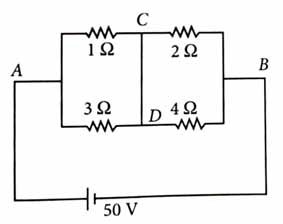
A constant voltage of 50 V is maintained between the points A and B of the circuit shown in the figure. The current through the branch CD of the circuit is       [2025]

[IMAGE 191]-------------

  • 2.5 A


  • 3.0 A


  • 1.5 A


  • 2.0 A


(4)

[IMAGE 192]---------------------------------------

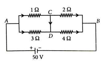
Let potential at junction C be x

        x-501+x-503+x-02+x-04=0

        12x-600+4x-200+6x+3x=0

         25x-800=0

or      x=80025=32V

Current through 1Ω resistance

         I1=50-321=18A

Current through 2Ω resistance

        I2=32-02=16A

   Current through branch CD is

        ICD=I1-I2=18-16=2A


Q 2 :    

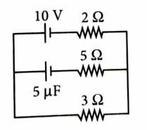
The steady state current in the circuit shown below is            [2024]

[IMAGE 193]

  • 0.67 A


  • 1.5 A


  • 2 A


  • 1 A


(3)

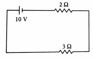
In steady state capacitor acts as an open circuit.

[IMAGE 194]---------------

So, the circuit will become

Req=2+3=5Ω

V=10V

I=VReq=105=2A


Q 3 :    

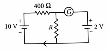
If the galvanometer G does not show any deflection in the circuit shown, the value of R is given by         [2023]

[IMAGE 195]

  • 100 Ω


  • 400 Ω


  • 200 Ω


  • 50 Ω


(1)

Since galvanometer shows no deflection, thus voltage across R is 2V.

Now, voltage across R is, V=10R400+R

or    2=10R400+R    R=100Ω


Q 4 :    

The potential difference (VA-VB) between the points A and B in the given figure is                [2016]

[IMAGE 196]

  • -3 V


  • +3 V


  • +6 V


  • +9 V


(4)

[IMAGE 197]

VAB=VA-VB=2×2+3+1×2=9 V