Q 1 :    

A bulb and a capacitor are connected in series across an ac supply. A dielectric is then placed between the plates of the capacitor. The glow of the bulb     [2024]

  • increases


  • remains same


  • becomes zero


  • decreases


(1)       

          As dielectric is placed, capacitance will increase.

            XC=1Cω

           It means the capacitive reactance decreases,so impedance of circuit decreases. Hence current increases. So power increases. So glow of the bulb increases.


Q 2 :    

In an a.c. circuit, voltage and current are given by:

V=100sin(100t) V

and I=100sin(100t+π3)mA respectively.

The average power dissipated in one cycle is              [2024]

  • 10 W


  • 2.5 W


  • 25 W


  • 5 W


(2)   

            Pavg=Vrms Irmscos(Δϕ)

                   =1002×100×10-32×cos(π3)=2.5W


Q 3 :    

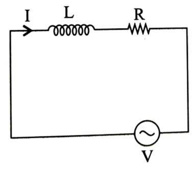
A series L, R circuit connected with an ac source E=(25 sin 1000t)V has a power factor of 12. If the source of emf is changed to E=(20 sin 2000t)V, the new power factor of the circuit will be                 [2024]

  • 12


  • 13


  • 15


  • 17


(3)     

         For first source power factor

          cosϕ=RZ=RR2+ω2L2

         12=RR2+ω2L2R2+ω2L2=2R2

         R=ωL

          for second source, ω'=2000=2ω

          Power Factor = RR2+ω'2L2

          =ωLω2L2+4ω2L2=ωL5ω2L2=15


Q 4 :    

An AC voltage V = 20 sin 200πt is applied to a series LCR circuit which drives a current I=10sin(200πt+π3). The average power dissipated is      [2024]

  • 21.6 W


  • 200 W


  • 173.2 W


  • 50 W


(4)   

           <P>=Irms Vrmscosϕ

                      =202×102×cos60°=50W


Q 5 :    

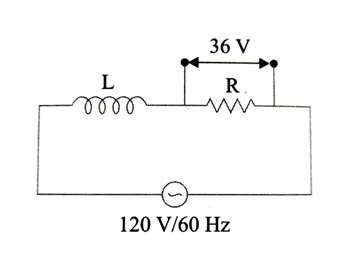
A coil of negligible resistance is connected in series with 90 Ω resistor across 120 V, 60 Hz supply. A voltmeter reads 36 V across resistance. Inductance of the coil is      [2024]

  • 0.76 H


  • 0.286 H


  • 2.86 H


  • 0.91 H


(1)

36=IrmsR

36=120XL2+R2×R

R=90Ω36=120×90XL2+902

XL2+902=300

XL2=81900XL=286.18Ω

ωL=286.18 

L=286.18376.8=0.76H


Q 6 :    

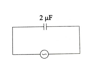
An alternating emf E=1102sin100t volt is applied to a capacitor of 2μF, the rms value of current in the circuit is __ mA.                 [2024]


(22)

Erms=E02=11022=110 V

Irms=ErmsXc=Erms·ωC

=110×100×2×10-6=22×10-3 A


Q 7 :    

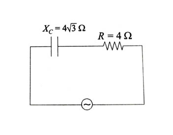
A capacitor of reactance 43Ω and a resistor of resistance 4Ω are connected in series with an AC source of peak value 82V. The power dissipation in the circuit is ______ W.              [2024]


(4)

Z=R2+(XL)2=42+(43)2=8Ω

Vrms=V2=822=8V

Irms=VrmsZ=88=1A

Power dissipation  P=VrmsIrmscosϕ

cosϕ=RZ=4(43)2+42=448+16=48=12

 P=8×1×12=4W


Q 8 :    

Given below are two statements: One is labelled as Assertion (A) and the other is labelled as Reason (R).

Assertion (A) : Choke coil is simply a coil having a large inductance but a small resistance, Choke coils are used with fluorescent mercury-tube fittings. If houehold electric power is directly connected to a mercury tube, the tube will be damaged.

Reason (R) : By using the choke coil, the voltage across the tube is reduced by a factor (R/R2+ω2L2), where ω is frequency of the supply across resistor R and inductor L. If the choke coil were not used, the voltage across the resistor would be the same as he applied voltage.

In the light of the above statements, choose the most appropriate answer from the options given below:          [2025]

  • Both (A) and (R) are true but (R) is not the correct explanation of (A).


  • (A) is false but (R) is true.


  • Both (A) and (R) are true and (R) is the correct explanation of (A).


  • (A) is true but (R) is false.


(3)

I=VR2+ω2L2, VR=RR2+ω2L2V


Q 9 :    

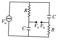
For ac circuit shown in figure, R = 100 kΩ and C = 100 pF and the phase difference between Vin and (VBVA) is 90°. The input signal frequency is 10x rad/sec, where 'x' is ________ .          [2025]


(5)

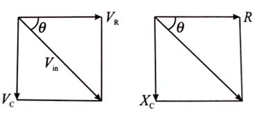
Input voltage

θ+θ=90°; θ=45°

tan θ=XCR

XC=R  1ωC=R

ω=1RC=1100×103×100×1012=1012107=105


Q 10 :    

An inductor of reactance 100Ω, a capacitor of reactance 50Ω, and a resistor of resistance 50Ω are connected in series with an AC source of 10 V, 50 Hz. Average power dissipated by the circuit is ________ W.          [2025]


(1)

P=VrmsIrmscos ϕ

P=Vrms×VrmsZ×RZ=Vrms2×RZ2

Z=R2+(xLxC)2

Z=502Ω

P=100×502500×2=1 W