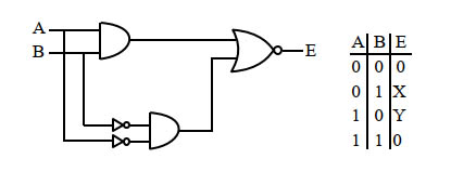
Q 1 :    

ldentify the logic gate given in the circuit                     [2024]

  • NOR gate


  • NAND gate


  • OR gate


  • AND gate


(3)

Y = A + B, Hence OR gate


Q 2 :    

Following gates section is connected in a complete suitable circuit.

For which of the following combination, bulb will glow (ON)                      [2024]

  • A  = 0, B = 0, C = 0, D = 1


  • A = 1, B = 1, C = 1, D = 0


  • A = 1, B = 0, C = 0, D = 0


  • A = 0, B = 1, C = 1, D = 1


(3)

Bulb is only on when across the bulb, signals are opposite → 0,1 or 1,0

A → Signals are 0 and 0

B → Signals are 1 and 1

C → Signals are 0 and 1

D → Signals are 0 and 0

So, the bulb is on only in option C.


Q 3 :    

The output (Y) of logic circuit given below is 0 only when                  [2024]

  • A = 1, B = 0


  • A = 0, B = 0


  • A = 0, B = 1


  • A = 1, B = 1


(2)


Q 4 :    

The correct truth table for the following logic circuit is:                   [2024]

  • A B Y
    0 0 1
    0 1 1
    1 0 0
    1 1 0


  • A B Y
    0 0 1
    0 1 1
    1 0 0
    1 1 1


  • A B Y
    0 0 0
    0 1 0
    1 0 0
    1 1 1


  • A B Y
    0 0 0
    0 1 1
    1 0 0
    1 1 1


(2)

By Boolean expression

Y=A¯+A.B

A B Y
0 0 1
0 1 1
1 0 0
1 1 1


Q 5 :    

The output Y of following circuit for given inputs is               [2024]

  • A.B(A+B)


  • A.B


  • 0


  • A¯·B


(3)

Y=A¯·B·(A+B¯)

=A¯·B·A+A¯·B·B¯

=A¯·A·B+A¯·B·B¯

=0+0=0


Q 6 :    

In the truth table of the above circuit, the values of X and Y are           [2024]

  • 1, 1


  • 1, 0


  • 0, 1


  • 0, 0


(1)

For x

For y


Q 7 :    

The truth table of the given circuit diagram is :               [2024]

  • A B Y
    0 0 1
    0 1 0
    1 0 0
    1 1 1


  • A B Y
    0 0 0
    0 1 1
    1 0 1
    1 1 0


  • A B Y
    0 0 0
    0 1 0
    1 0 0
    1 1 1


  • A B Y
    0 0 1
    0 1 1
    1 0 1
    1 1 0


(2)

Y=A·B¯+A¯·B

This is XOR gate


Q 8 :    

Identify the logic operation performed by the given circuit.          [2024]


  • AND


  • NOR


  • NAND


  • OR


(4)


Q 9 :    

The truth table for this given circuit is              [2024]

  •  

    A B Y
    0 0 1
    0 1 1
    1 0 1
    1 1 0


  • A B Y
    0 0 1
    0 1 0
    1 0 1
    1 1 0


  • A B Y
    0 0 0
    0 1 1
    1 0 0
    1 1 1


  • A B Y
    0 0 0
    0 1 0
    1 0 0
    1 1 1


(3)


Q 10 :    

The output of the given circuit diagram is                   [2024]

  • A B Y
    0 0 0
    1 0 0
    0 1 0
    1 1 1


  • A B Y
    0 0 0
    1 0 1
    0 1 1
    1 1 0


  • A B Y
    0 0 0
    1 0 0
    0 1 0
    1 1 0


  • A B Y
    0 0 0
    1 0 0
    0 1 1
    1 1 0


(3)